Step 3 Guide
How to take measurements
Accurate measurement is essential to ensure a professional installation.
In Step 1, identify the potential anchor points and take measurements between them.
At this stage, measurements can have a slight tolerance of a few centimetres. The final dimensions will be confirmed once the anchors are installed.
In Step 2, once the anchors are in place, precise measurements must be taken.
IMPORTANT: All required measurements always refer to the anchor points, not the actual fabric size.
The system will automatically calculate the sail’s dimensions.
Measuring the Space
STEP 1: Use a rigid tape measure to measure the area where you want to install the sail, considering obstacles such as walls, trees, or other elements that may affect the installation.
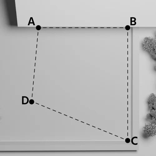
STEP 2, use the measuring tape provided with the anchor kit to accurately measure corners and the sail’s diagonal.
Measurements must always be taken from anchor point to anchor point.
IMPORTANT: If you decide to install the sail with an inclined winding roller, the actual distance between corner A and corner C will be greater than in a perfectly horizontal installation. This happens because tilting the roller increases the length compared to a parallel-to-ground setup.
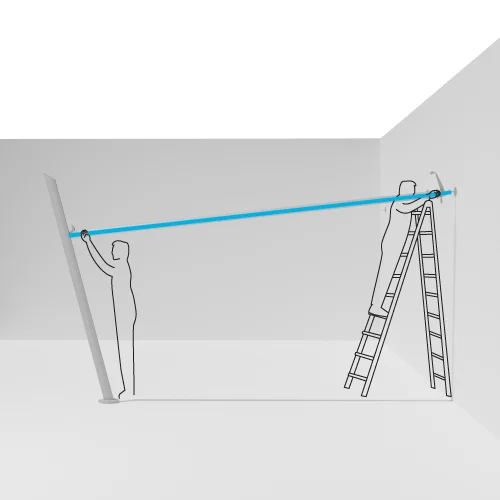
Identifying Side AC (Winding Roller)
The AC side is conventionally identified as the winding roller.
In a quadrilateral (four-cornered sail), AC corresponds to the diagonal.
In a triangular sail (isosceles, scalene, or equilateral), side AC corresponds to one of the sides.
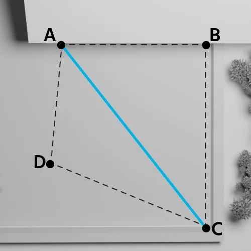
Example: Quadrilateral Shape
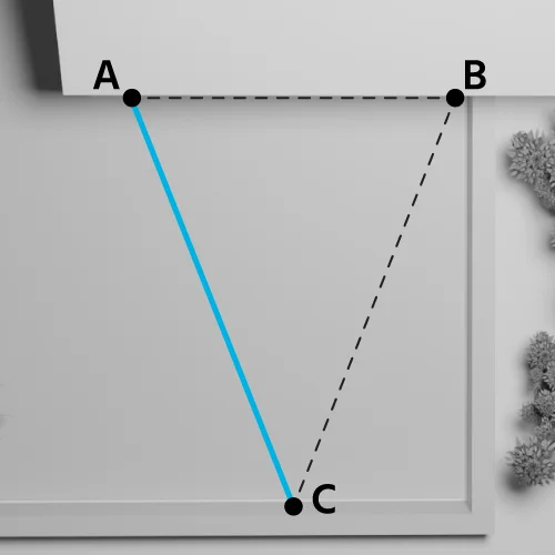
Example: Isosceles, Scalene, and Equilateral Triangle
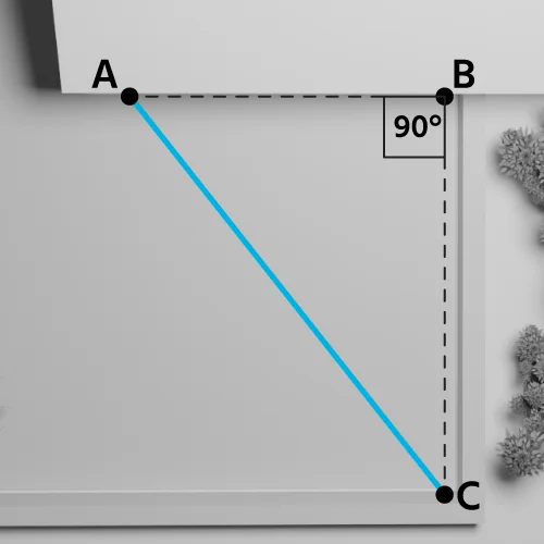
In a right-angled triangle, side AC is the hypotenuse.
Example: Right-Angled Triangle
IMPORTANT: See the corner constraints for corners A and C in the specifications at the bottom of the page.
Motor Installation Corner
Corner A is always where the motor is installed, serving as the main reference point for configuring the sail.
Defining this corner first allows for precise placement of the other anchor points, ensuring a correct and balanced installation.
Corner A should be the highest point of the boom.
Measuring the Winding Roller
The length of the winding roller (side AC) has a tolerance of 2.5 cm per side. This measurement must be taken with extreme precision in STEP 2, once the anchors are installed.
Sail Inclination
The winding roller can be inclined.
The maximum allowable inclination for side AC is ± 25% of the winding roller’s length.
Example:
If the winding roller (side AC) is 8 metres (800 centimetres) long
Maximum inclination = 800 / 100 x 25 = 200 centimetres
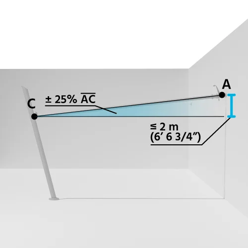
IMPORTANT: If you install the sail with a tilted winding roller, the actual distance between corner A and corner C will be longer than in a perfectly horizontal installation. This happens because tilting the roller increases the length compared to a parallel-to-ground setup.
TIP: It is recommended NOT to tilt the roller towards corner A, as this is where the motor is.
Constraints for the Motorised Roll-up Sail
General Constraints
To ensure the project’s feasibility, it is essential to follow specific technical constraints when designing the motorised roll-up sail.
- Corner A: This is always the point where the motor is installed, serving as the primary reference for the entire configuration.
- Side AC: This diagonal corresponds to the winding roller and must adhere to specific measurements to ensure stability and optimal fabric tension.
- AC Side Dimensions:
- Minimum length: 210 cm
- Maximum length: 800 cm
Special Constraints for Triangular Sails
- Maximum area: 20 m²
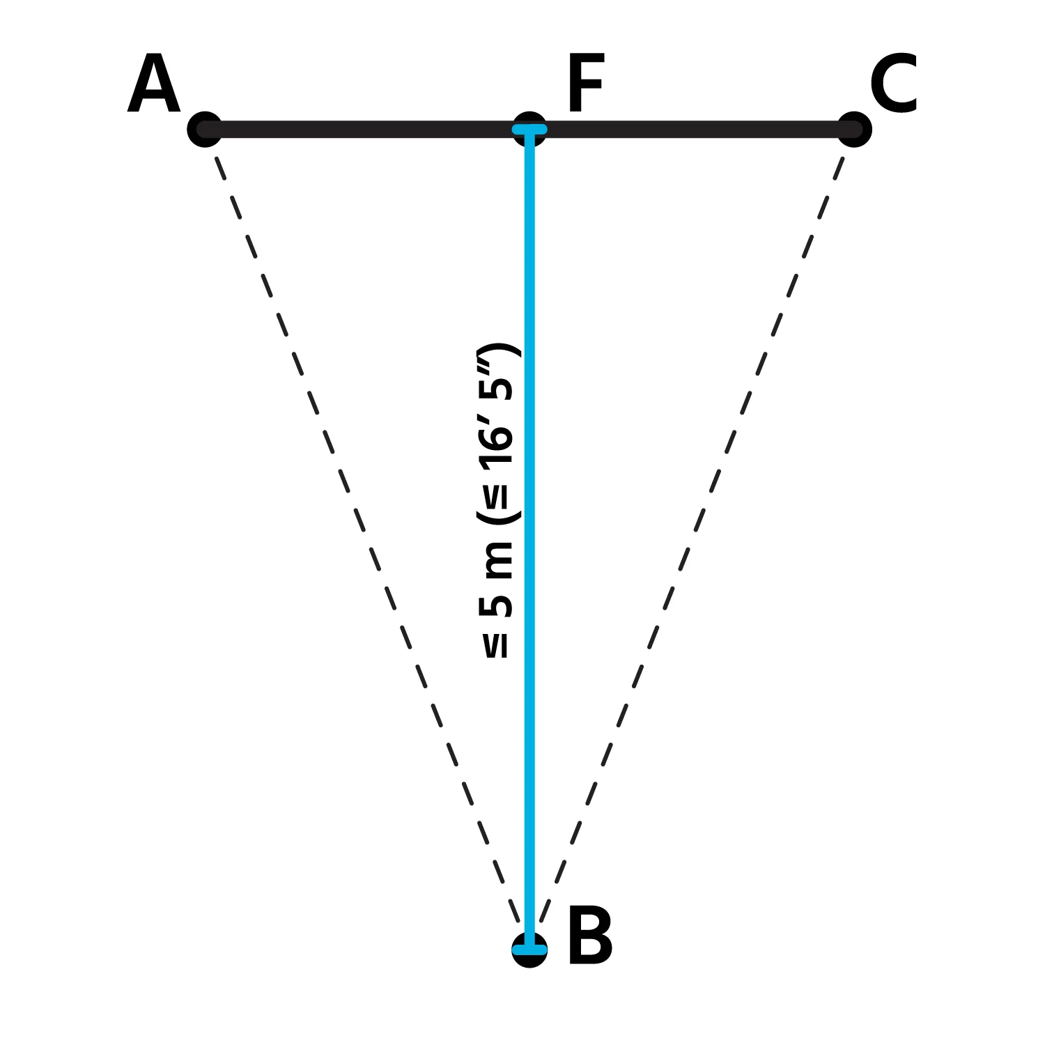
- BF measure, perpendicular to AC (winding roller), can measure a maximum of 5 metres.
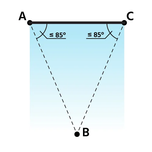
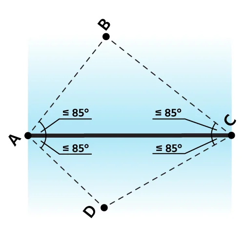
- Angles A and C must be ≤ 85°.
For simplicity, corner B must remain within the winding roller’s outline to ensure proper rolling.
Special Constraints for Quadrilateral Shapes (Square, Rectangle, Trapezoid)
- Maximum area: 30 m²
- Angles A and C must be ≤ 85°.
For simplicity, corners B and D must remain within the winding roller’s outline to ensure proper rolling.
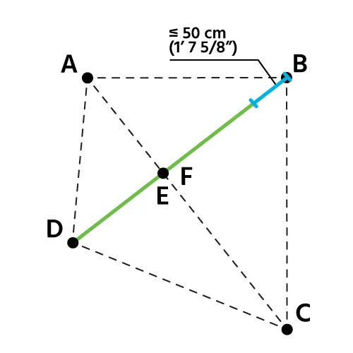
- The difference in extension (length) between measurements DE and BF must not exceed 50 cm, as shown in the diagram.
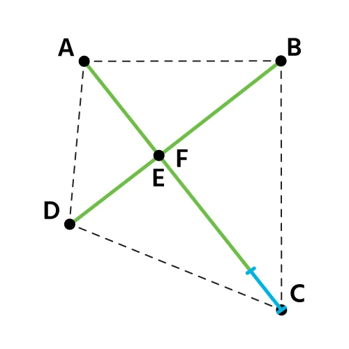
- The AC side (winding roller) must always be longer than sides DE and BF, as illustrated.










 English GB (English)